Hardware Platforms
DC Motor Control Shield with BTN9970LV and BTN9990LV
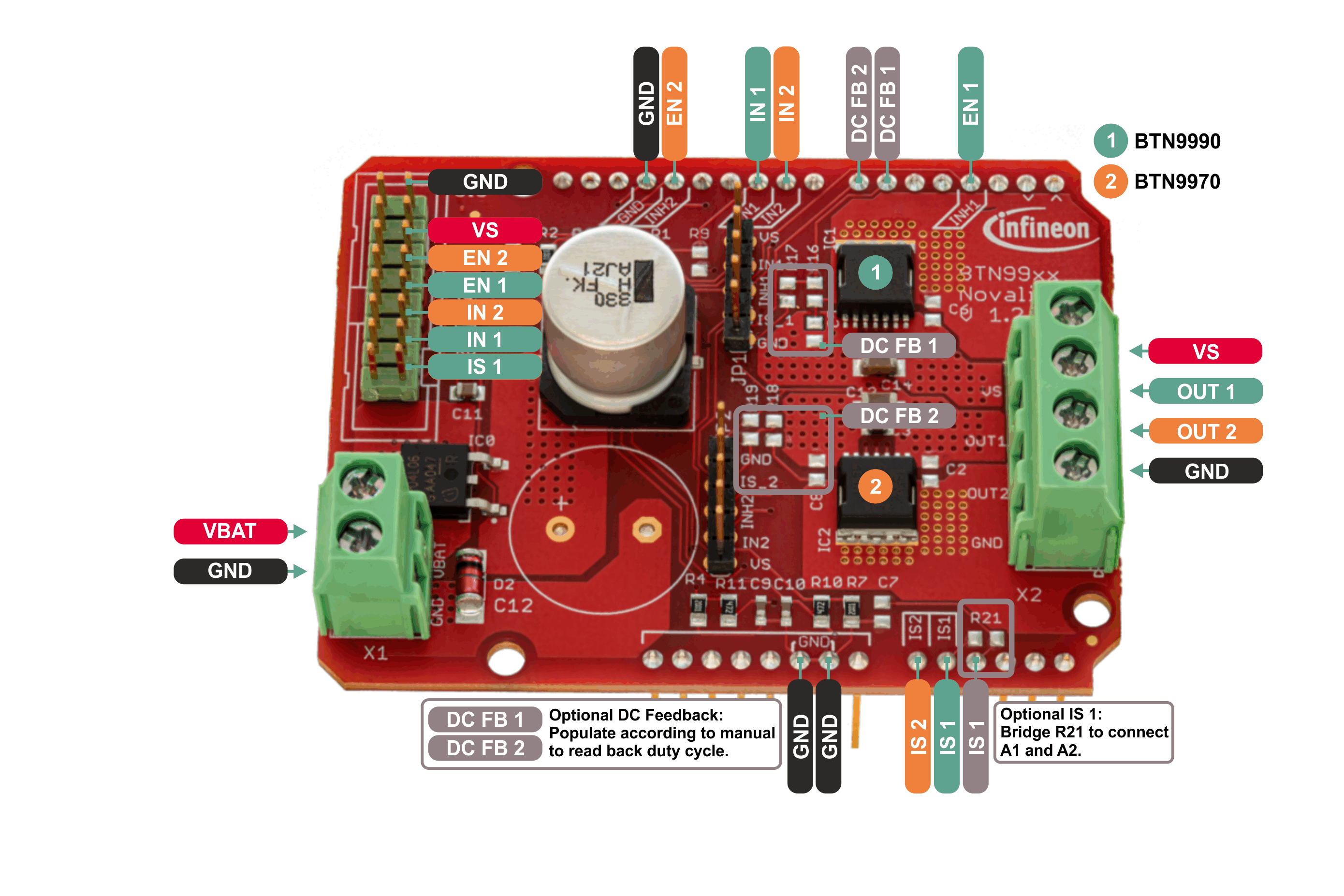
Pinout Diagram
Pin Description
Arduino Pin |
Symbol |
Type |
Function |
|---|---|---|---|
- |
VBAT |
Supply |
Supply voltage for half bridges (connected to VS through reverse battery protection). |
- |
VS |
Power output |
Supply voltage for external load. |
GND |
GND |
Supply |
Ground |
3 |
EN 1 |
Input/digital |
Enable pin (connected to inhibit input) of device 1 (BTN9990). |
6 |
DC FB 1 |
Output/PWM |
Duty cycle read back output of device 1 (BTN9990). Not connected by default, can be enabled by populating R16 and R17 according to the board manual. |
7 |
DC FB 2 |
Output/PWM |
Duty cycle read back output of device 2 (BTN9970). Not connected by default, can be enabled by populating R18 and R19 according to the board manual. |
9 |
IN 2 |
Input/PWM |
PWM/digital input of device 2 (BTN9970). Use this pin to set the power output of the device to VBAT (1) or GND (0). |
10 |
IN 1 |
Input/PWM |
PWM/digital input of device 1 (BTN9990). Use this pin to set the power output of the device to VBAT (1) or GND (0). |
13 |
EN 2 |
Input/digital |
Enable pin (connected to inhibit input) of device 2 (BTN9970). |
A0 |
IS 2 |
Output/analog |
Diagnosis pin of device 2 (BTN9970). |
A1 |
IS 1 |
Output/analog |
Diagnosis pin of device 1 (BTN9990). |
A2 |
IS 1 |
Output/analog |
Diagnosis pin of device 1 (BTN9990). Not connected by default, can be connected to A1/IS1 by bridging R21. |
- |
OUT 1 |
Power output |
Power output of half bridge device 1 (BTN9990). |
- |
OUT 2 |
Power output |
Power output of half bridge device 2 (BTN9970). |
Supported MCU Platforms
In principle, the library is supported by any Arduino compatible MCU platform. Its Arduino core needs to implement the Arduino reference language.
Verified MCU Boards
The library examples have been built and successfully executed on the following hardware platforms:
MCU Platforms |
|---|
Find out which boards are build checked under continuous integration here.
Known Issues
When using the Infineon XMC for Arduino boards: The analog input pins cannot be set as analog outputs, which affects current and temperature measurement on these boards. If you want to use this functionality please use jumper wires to different pins.
When using the Infineon XMC for Arduino boards: PWM functionality works only on XMC for Arduino >= 2.0.1